Greetings! This Fall, I built the first of 2 planned practice amps. Inspired by simple
1950’s tube guitar amps I too kept it simple. In those Golden-era amplifiers, you plug the
guitar in 1 jack, the speaker in the other and hit the switch. Modern
solid state guitar amplifiers with effect loops, frequency compensating gain control stages and features
galore may just complicate things in the guitar - amp - player interface. While perhaps cool and fancy, these added stages may carry high-value
resistors that boost op-amp input current noise and also increase resistor-related
Johnson noise too.
My goal =
make a low noise jazz / clean guitar amp as opposed to a low distortion,
high-fidelity practice amplifier. I remember having to turn the volume pot on
my Stratocaster to 0 between songs in my Marshall 50 - 100 Watt amp days of lore.
The amp sounded great, but was super noisy unless the rest of the band was
playing loudly to drown the amp noise out. At my age, a quiet amp seems desirable.
Note, I completely redesigned the preamp on November 15th after first posting this amplifier on November 6, 2022. Two things changed to trigger that : [ 1 ] I moved to 10 inch speakers [ 2 ], I moved to playing Fender Telecaster guitars 95% of the time instead of an arch top. With my back and wrist pain, the Telecaster proves much easier to play --- and also it's Leo Fender's gift to humanity. Such a joy to play. Thus, I re-designed my practice amp around playing a Telecaster through a 10 inch speaker. The result is a basic preamp with few AC coupling capacitors in the signal path.
Project Index
1. Preamplifier and Tone stages 2. Power Amp
3. Power Supply
4. Miscellaneous Bench Notes
5. Video Links (only 1, but more coming later)
1. Preamplifier and Tone Stages
Above — Input stage also showing ground loop reduction techniques to eliminate 60 cycle hum.
In tube amps, we employ our quietest 12AX7 or alternate preamp tube in V1 -- or the first preamp position, since all arising noise gets boosted down the signal chain. Same for solid state design. We seek to input the guitar signal, filter off radio frequency interference, plus control & boost signal amplitude while adding minimal noise and hum.
I prefer a 12 K Ω input resistor for Telecaster guitars and I didn't have any in metal film, so placed two 22 K Ω resistors in parallel got get the 11K Ω shown. For picofarad level caps, I use MLCC types with C0G temp compensation in all of my projects from AF to microwave. Both the positive and negative op-amp DC voltage pins get a 100 nF capacitor shunt to ground as close to the op-amp package as possible. It's OK if the temperature compensation of those particular 100 nF MLCC caps is X7R from my experiments.
An active gain control keeps the noise down. Like in tube amps, many solid state guitar amp input systems maximally boost the signal in the input stage(s) and then immediately attenuate it using a volume pot. This functionally works OK, but when a stage is operating at maximal gain, it’s also making maximum noise and today we may choose to apply noise - reducing active gain circuits with our op-amp & transistor design work.
I chose a warm, jazz guitar amp voicing inspired by the lovely Gibson amps of the 1950’s.
The above schematic also shows 1 ground loop prevention strategy to consider. Each stage including the power supply and PA are electrically isolated from the chassis by carving away copper around the mounting bolts + nuts. A single, insulated ground wire from each isolated board goes to the master star ground node located on the power supply board. Classic star grounding.
At the guitar input jack, the chassis becomes connected to the input jack bolt ground lug when you tighten the bolt. An insulated wire from the input jack ground lug runs to the EARTH ground on the AC receptacle. The non-grounded input jack lug coax centre runs to the op-amp input, however, the braid of the coax at this end goes to the star ground system as shown. The chassis gets connected to the star ground system only through the coaxial braid at the guitar input end of the coax. The result is no hum. I use RG-174, but any coax or shielded wire may work OK. No other coaxial cable are used in this guitar amplifier.
Above — The entire preamp went onto this board. This photo shows an earlier iteration. I place some local DC filter capacitors on each board in my projects. On this board, 100 µF and 100 nF were placed. The blue and white wires move DC to the op amps positive and negative terminals. A guitar signal flows down copper wires along with its DC supply.
I employed genuine Texas Instruments brand NE5532s with a typical input noise density of 5nV/√Hz for the 2 op-amps that make the preamp. I enjoy this lovely, quiet part.
Above — The tone stack, buffer, plus final preamp stage with master volume control. This board uses a hybrid approach to tone control — a passive 1960's tone stack for bass, middle and treble -- plus active bass with a Baxandall circuit. A regular Fender/Marshall style passive tone stack cuts too much bass for my needs. The active bass control turnover frequency is 80 Hertz and offers ~ 15 dB cut or boost. I kept the impedance higher to allow hard boosting with no distortion or noise. This amp with a 10 inch speaker gives more bottom end than many solid state guitar amps with a 12 inch speaker.
The scaled to nearest standard value capacitor, classic Fender tone stack RC network use relatively low value potentiometers plus higher capacitance to reduce noise. With the active bass, this tone circuitry offers a wide variation in tone control. Fender / Marshall et al. tone stacks work best driving a high impedance, thus it drives a nJFET follower with 1.7 mA source current. This, in turn, drives the Baxandall circuit with a preferable low impedance.The FET drain is RC low-pass filtered and connected to the regulated, positive op-amp supply rail.
The master volume active gain stage uses the topology from first preamp stage — the additional resistor ( 1K here ) causes the 10K pot to change gain in a more linear fashion. As you age, your near vision worsens --- and also when playing, room light is often poor, so you might just adjust volume knobs “by ear”. This amp sounds very loud for 12.4 Watts and when cranked up, vibrates the walls in my den at low frequencies with a 10 inch speaker.
Above —The complete preamp board with some test wires and a temporary 1/4 inch input jack for bench testing.
2. Power Amp
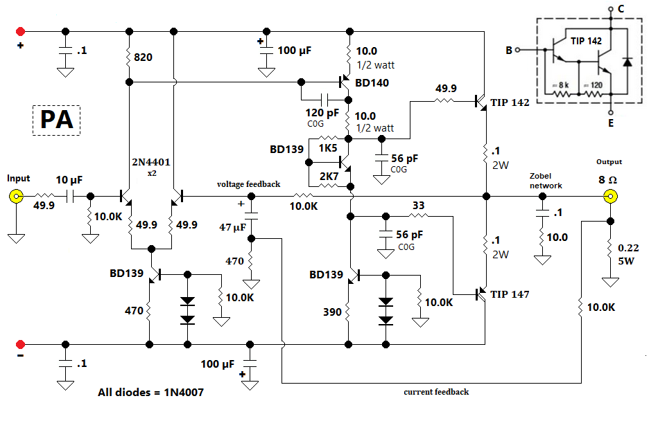
Above — The PA schematic.
Since this is a low DC voltage amp with plus/minus ~ 20.85VDC (unloaded) on the rails, common, low-voltage transistors such as the 2N4401 emitter coupled pair shown will work in the transconductance amp. All resistors = 1% metal film types as possible. Most are rated at ¼ watt. The emitter couple pair get degenerated with 49.9 Ω resistors to boost linearity. Some designers leave them off, however, PA distortion will increase dramatically. I think 49.9 Ω is a reasonable value for guitar PA transconductance amplifiers.
The pair get sunk by a current source biased for 1.48 mA. Even a simple current source design like I used greatly surpasses old-school long tail resistor biasing since the high collector resistance helps boost differential balance to reduce noise and distortion. For my current sources, I opted to use cheap BD139 transistors instead of small signal TO-92 types.
This PA lacks any protection circuitry for when something goes wrong. Thus, I overbuild to keep it running when something does go wrong. Guitar amps may suffer lots of punishment including when you are building and testing them. I feel that the current sensing and limiting protection circuits found in many commercial PA circuits move away from the spirit of the 1950’s style amplifiers where simplicity proved a key feature. After all, if my PA fries a transistor or 2, I can fix it.
The voltage amp or VAS = a genuine NXP brand BD-140 PNP job. I tried 5 PNP BJT’s in this slot: the venerable high voltage classic KSA-1381, a BF-423, a BD-238, the BD-140 -- and a suspect bootleg MJE-350. The MJE-350 gave poor gain and went in the garbage. The KSA-1381 offered the most gain but seemed a bit overkill -- and the others provided similar gain and PA clean signal power with bench testing. In the end, the BD-140 seemed the logical choice for a practice amp. Since I wanted this PA to offer good gain, I only degenerated the VAS emitter by 10 ohms which may lead to instability in some designs. You’ll commonly see resistor values of 33-47 ohms used in some commercial designs. Increasing emitter degeneration boosts stability plus noise while the lowering the PA gain. The measured PA voltage gain = 56.
The most sensitive part of the entire PA is the collector of the VAS
transistor. I found a strange phenomenon. When I put the 'standard' 68 to 120 pF cap
between its collector and base, HF oscillations occurred and I saw
distortion of the PA output when looking in my PA in a DSO with low
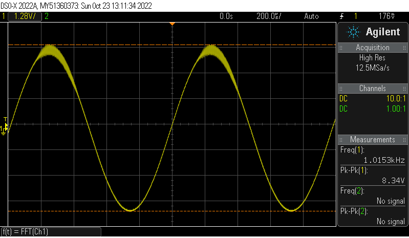
levels of 1 KHz signal generator input. I actually remembered to save
these image files as an FFT and a sine wave:
Above — Distortion caused by the VAS feedback capacitor that went away when I cranked the input signal up above 10 Vpp. When I removed the cap, no distortion appeared at low levels, but re-emerged at high levels of input drive. I left out the 120 pF feedback cap and instead installed a 10 Ω resistor plus 56 pF shunt capacitors on each arm driving the Darlington complementary power followers. This eradicated all instability at all input signal levels.
Sadly, when I built the master volume gain control circuit and connected that up to the PA and then my signal generator to its input, the distortion problem re-emerged! Thus, I added back the 120 pF feedback capacitor and the PA stabilized at all signal levels. Likely, increasing the VAS emitter degeneration would have helped, but I can live with 3 small capacitors stabilizing my PA. I find it best to add stabilizing capacitors after you build and look at your PA with a dummy load, signal generator and DSO (‘scope). Then decide what capacitors you need add to remove HF oscillations.
Continuing on ... a similar current source biased for 1.77 mA sinks the VAS & output driver stack. I stopped using diodes for biasing the output followers in my PA stages – rather, I prefer to run a single BD-139 with fixed bias for simplicity. The 1K5 resistor going from collector to base gets soldered in. Then, I temporarily solder in a 5K pot between the base and emitter nodes and tweak the pot until the crossover distortion disappears. The pot is then removed and measured with an ohmmeter. A nearest standard value resistor ( in this case 2K7) gets substituted for the pot and then a final check is done with a DSO with or without an FFT as you can see easily crossover distortion in a sine wave on your 'scope. You might even further check this by ear into a speaker while playing single notes on the thicker guitar strings. The voltage across the power follower biasing NPN transistor is just over 2.1 VDC.
For guitar amp PAs, I now prefer using complimentary Darlington style transistors like the TIP142/147 pair. It simplifies design and works well. Other transistors I may evaluate in the future include the BDX33C/BDX34X, BDW93C/BDW94C and the TIP 127/TIP 122.
Above — The maximum clean signal power into a dummy load with all harmonics < 60 dBC. Very happy.
Above — Heat sinks fashioned for the TIP 142/147 power follower pair. I ran the amp in test mode with signal generator + dummy load at 10 Watts for 30 minutes and the PA temperature measured ~29 degrees C. Hulky 10 amp transistors on big heat sinks in a low power guitar amp should last a long time.
3. Power Supply
Above — The split DC voltage power supply. I employ no switch as my amps AC plug into a certified, high-grade, commercial power bar that is turned off and then unplugged when the amp is not in use. Power supplies involve voltage + current that may cause injury, death or fire. Only work on power supplies and/or amplifiers if you are a certified to do so. You incur all liability arising from all electrical equipment problems, accidents, or mistakes. Safety. Safety. Safety.
LED apparent brightness is adjusted by the current limiting resistor to each. 1 LED monitors each rail in my designs. Orange = positive is my personal standard. If your PA is self-oscillating, you might even see an LED flicker.
Above — Twins! I purchased these 2 light, low power transformers for my 2 practice amps. The 25 VAC RMS centre-tapped transformer [1L6625] went into the GAA-12 amp. The 20 VAC RMS transformer will go in an even smaller practice amp for our living room. It will hide it on a bookshelf and drive a 10 inch speaker.
Above — The genuine Nichicon brand capacitors that went on the power supply board to filter. We now have to worry about bootleg transistors, capacitors, power resistors, linear ICs and more. Such as pain! Caveat emptor.
Finally, the op-amp voltage regulators went on their own small PC board:
Above — Parts for the op-amp voltage regulators. Again, I overbuild. These hulky, slow transistors will last longer than I will -- and provide extra stiff voltage regulation.
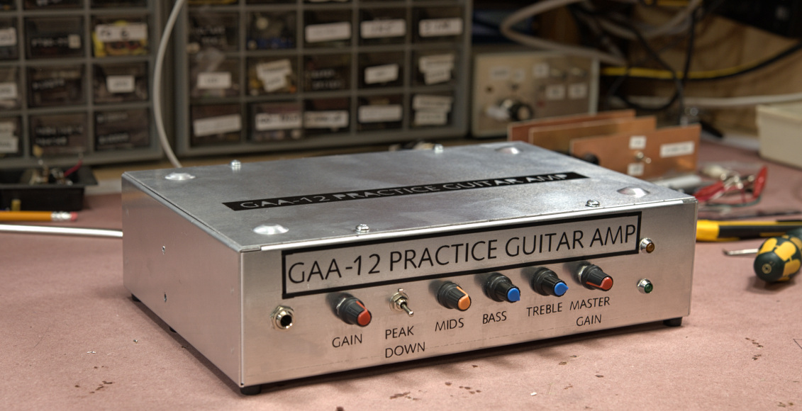
Continuing on... a couple of the latest amp chassis photos I call the passive tone stack 'bass', the fat control:
4. Miscellaneous Bench Notes
Above — A bench test jig that contains a TIP 142 and TIP 147 pair that I use for PA board development.
Above — The reverse view of the PA test jig seen from the opposite angle. It contains a pair of 0.22 Ω resistors, a Zobel network and an isolated speaker jack. The yellow wire passes through to the 0 volt centre rail.
Above — The GAA -12 PA board under test with 1 or 2 temporary parts attached. Since the PA transistors are normally mounted in heat sinks in your amp chassis & connected with wire or PC board paths to the rest of the PA circuitry, this test jig mimics them well. You can instant tell if you made a mistake or parts are broken etc..
When I mounted the PA board in the amp chassis and the PNP transistor did not work, I knew it was not the PA board at fault. It turns out that the 0.22 Ω power resistor connected to the PNP follower inside the amp chassis was open circuit. I didn't have any more, so, then changed both to 0.1 Ω emitter resistors as I had several of these in stock. From now on, I'm sticking with Vishay brand wire wound resistors as bootleg power resistors have sadly made their way into our parts bins. I prefer 0.22 Ω emitter resistors to boost stability in the power follower pair.
Above 2 pictures — The transformer and power supply, input, master volume/ DC regulator & PA boards -- plus the heat sinks all mounted in the chassis. The guitar amp input is as far away from the power supply as possible.
Above — Reverse view of the the entire preamp module under development. This likens a blank canvas with 2 op amps plus all the potentiometers installed. It's now up to you to install the right combination of resistors + capacitors to make a nice guitar amp. It's really that simple in 1 aspect. This entire module goes into the amp chassis and the pots line up with the holes drilled in the metal chassis.
5. Video Links (only 1, but more coming eventually later)
My videos look better on YouTube proper
The only video so far is this short 1 already posted on Oct 22, 2022


No comments:
Post a Comment