
Many amateur experimenters stay in the familiar comfort zone
of HF. A small number venture into VHF, and even fewer devote time designing, building and operating for the UHF & microwave spectrums.
Outside of amateur radio, broadband UHF radio operation
dominates the airwaves: data or voice
communications on smart phones hum along nonstop on WAN, LAN, cellular, PCS, PSTN and
satellite networks. Then too, we’ve got
the ISM bands that backbone industry and commerce @ UHF and higher spectrums
for multiple groups, including radio astronomers.
Also digital television broadcasting standards may involve the UHF spectrum, and so, a pattern emerges: UHF circuitry sending data that's controlled by CPUs.
This UHF proliferation benefits us experimenters by providing an excellent bevy
of fast parts such as 25+ GHz transistors, cheaper, more abundant transmission line + connector choices, numerous scientific articles, faster +
cheaper test equipment --- and loads of inspiration. To boot, many transmitting
circuits are low voltage and/or low
power – aka “QRP”. This is the new QRP ! Fresh, relevant, science-driven -- and supporting the marriage of code plus RF design in the new age via the latest tools, techniques and hardware.
The physics and challenges of RF design haven't changed however. For example, the Smith Chart still works perfectly, and measurement techniques remain the same. However, some differences become quickly obvious as you plow in: 1 stark example == resonator Q. Vitamin Q gets hard to come by as we move up in frequency. Further, the ease + slack and forgiveness of HF quietly disappears and this proves both vexing and challenging to us builders.
Casual construction techniques work poorly at UHF. Consider
a Class A common emitter BJT amplifier: A poorly RF grounded emitter lead may add parasitic inductance that results in series feedback which degenerates the signal
and reduces amplifier gain.
Further, I’ve learned that a high bandwidth transistor amp designed and/or built poorly make frustrating oscillators, or, just offers low gain due to mismatch or instability. Unsurprisingly RF filters with poor RF grounding @ UHF poorly attenuate UHF. I'll show this graphically in the next section.
UHF design looks scary to some: you have to master the Smith Chart, obtain some fast transistors, and learn about microstrip techniques and so on.
Then comes the task of making your test bench. Yikes!
High bandwidth gear may equal high cost depending on what you build or purchase. For sure, you’ll need some form of a 50 Ω detector. My main UHF detector = a 3 GHz spectrum analyzer with a tracking generator. This allows me to measure with or without sweeping 1 or 2 port circuits. You also get a frequency counter in the RG + SA package -- so it seems like a good choice; at least for now.
I also designed and built a wide band return-loss bridge and plan to improve this design over time. I would love to own a network analyzer, but will hold off until I find an affordable unit with a bandwidth >= 10 GHz. 10 GHz? Yes, I hope to work 10 GHz EME using JTF4 mode with Doppler correction on homebrew gear 1 day.
My eventual goal @ UHF -- to design and build a UHF radio astronomy system looms in the background, however, first, I must learn to design and match amplifiers, tackle low phase noise, temperature-stable oscillators and learn how to make filters that work well into microwave.
I’ll blog some of my experiments starting today.
[1] Ugly Construction
RF signals follow the path of least impedance. This means plying double-sided copper clad board with the lower half serving as the microstrip ground plane. Currently, I use glass-fiber epoxy laminate FR-4, 1 ounce copper boards with 1.37 mil trace thickness and a substrate height of 1.6mm (1/16 inch).

Above — I got a deal on some MG-Chemicals FR-4 and will use it for all of my 2017 experiments. FR-4 is common, easily available and cost effective.
Permittivity, or the dielectric constant Er = ranges between batches and manufacturers of FR-4. I've read Er values from 3.9 to 4.8 and tend to use the standard 4.7. This means a 50 Ω stripline gets cut to a 2.9mm width.
Although, substrate thickness varies and insertion loss increase with frequency, I think we can manage OK with FR-4 copper clad laminate board at UHF. PTFE-based boards pose an option if we require critical impedances , λ fractions, or lower insertion loss as you move up in frequency.


Above — 4 square feet of FR-4 laid out on the lawn. These boards will hopefully bear some good experiments ahead.
RF Grounding

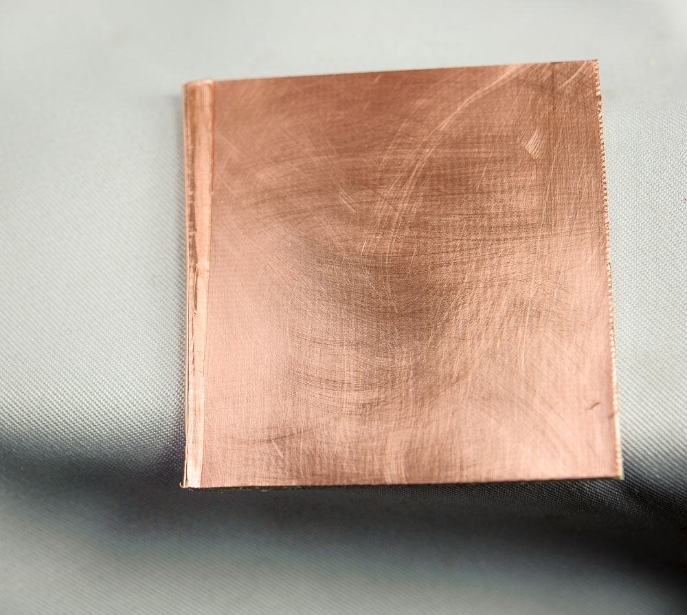
Above — A portion of an older, beat-up 12 inch by 12 inch 40 gauge copper sheet I use to connect the copper surfaces at all board edges. I just cut it with scissors. You can also smooth out the pieces before, or after cutting them.
I get this sheet copper from Monte Allums in the USA. Click for his link. I've also built tops for shielded RF boxes and resonator dividers with this stuff. Oh, and I shielded an electric guitar control cavity for someone using this Cu as well.

Above — An example edge dressing. We start with a small 2-sided piece of FR-4 and a cutting of Montee Allums 40 gauge copper sheet.
Above — I' ve folded the copper sheet over 1 edge. Looking a little uneven, it's clearly not my best effort, but on the other hand -- it will work fine. I scraped the copper sheet with the edge of the scissors so it lies flush against the FR-4 with no air gaps. Time to solder.

Above — The copper sheet gets wrapped around soldered on both sides. Then repeat for the other 3 FR-4 sides. When completed, you'll have a board ready for carving out strip lines or applying classic ugly construction when using B+ posts, connectors and capacitors as stand-offs.
A 2-sided FR-4 board with copper strips joining all edges will provide stalwart RF grounding from DC to VHF. For UHF we need to drill via holes and connect the 2 surfaces with copper wires strategically located wherever UHF ground is needed.
I'll demonstrate why with an actual experiment based on a 7- element low-pass filter that I designed to use the lumped-element inductors and capacitors I had on hand.
The inductors = Coilcraft 1008CS series wire wound on ceramic chips. These are in size 0805. Click for a datasheet. I've since stocked many values of these amazing parts in both size 0805 and 0603.

I then built a filter, but did not solder the copper edges together with Cu sheet metal and just use 1 via wire for the RF ground on each of the 4 caps.

Above — A sweep out to 3 GHz shows sub-optimal RF grounding leads to poor attenuation above ~1.5 GHz. This = a terrible filter.

Above — A sweep made after adding the copper edges and 1 more via wire to each of the 4 capacitors. While better than previous, attenuation poops out at 2.475 GHz.

Above — Final version swept after adding 2 more via wires to each of the 4 capacitors. Clearly soldering 4 copper via wires per ground node boosted the filter's attenuation at 3 GHz.


Above — The low-pass filter swept above.

Above — A MCL PLP-550 low-pass filter. This older filter suffered bent pins and I failed to get a short path for the 4 ground pins to the ground plane on the lower half of the board. 1 mm of wire length potentially could = 1 nH of stray L.

Above — Poor RF ground at UHF trashed the upper stop band of my poorly mounted MCL PLP-550 low-pass filter.

Above — I attempted to reduce the ground path lengths and also placed 2 via wires by each SMA connector. This boosted the UHF stop band somewhat. I'll take an entirely different approach when I redo this filter's breadboard 1 day.
I've learned the bitter truth about RF grounding @UHF -- and now RF ground lies foremost in my mind when I breadboard a circuit.
Multiple, short, low inductance via wires provide a low-impedance connection
to the ground plane below and in addition to improving RF bypass may reduce noise + interference.
[2] SAW based Oscillators
SAW resonators offer an easy way to generate a single frequency with a decent loaded Q to reduce oscillator single sideband phase noise when compared to LC, or varactor-tuned circuits @ UHF.
It's also possible to tune them as a VCSO ( voltage controlled SAW oscillator ). They see use in many commercial items such as garage door openers, chemical sensors and even wearable medical devices. You'll often view them in datasheets covering the range of 200 - 1200 MHz, although other frequencies are also available. The unloaded Q of a typical SAW device lies between 6 - 12K. That's much better than that of a VCO with the inductor cut out in the copper board (Q = 50 - 100) and tuned with varactor(s).
Of course, the variable SAW resonator lacks the wide tuning bandwidth needed for many projects -- UHF work proves all about compromise.
So far, I've built 7 or 8 SAW oscillators and many were crappy. Some of the problems included oscillation at an overtone, low output, parasitic oscillation, and not running at the correct SAW frequency.
I'll show an oscillator I built to use for OIP3 measurements of BJT amplifiers using my lab-grade HP signal source as the other tone for these 2 tone measures.


Above —The output of the feedback loop oscillator. If you take the signal from the collector, the AC voltage may run as high as 1.5 Vpp, but it's rich with harmonic energy. I sampled some output from the transistor base via a 0.5 pF capacitor. All caps < 100n were C0G temperature coefficient. Transistors such as the 2SC3583 offer tremendous gain at HF, so HF and even AF bypass is needed to keep circuitry stable.

Above — Output of the second transistor stage. I'll comment about the collector feedback bias in a later blog post. I attempted to match the output impedance to the 50 ohm input impedance of the MMIC, I did OK, but failed to account for stray reactances and also I didn't have caps less than 0.5 pF at the time. The 33 Ω resistor in series with the 22n lower its Q to stabilize the amplifier.

Above — Output of the final stage, a MMIC. I lost significant signal amplitude because my poor filter layout. My carved microstrip paths were too long and so, acted like inductors that detuned the filter and created some reflections. Of course, you never know this until after you've carved your breadboard. Still, this circuit works OK for amplifier, or mixer 2-tone measures and I learned a lot by designing and making it.
This was by far the most temperature stable SAW oscillator I've built.


Above — An experimental Butler SAW oscillator. When you remove the SAW resonator, the circuit still oscillated and needs to be within 5% of the SAW value or the frequency stability suffers. Further, the oscillator worked best with a tuned collector. I need to work on this some more. It doesn't take much to push this circuit into an overtone oscillator; intentional or not.
I'm always trying to boost the QL since SSB phase noise lies inversely proportional to the square of the loaded Q.

Above — The output signal with a tuned collector. Oscillators combine art, science and to some extent, a little luck.
[3] RF Amplifier
I'll show 1 experimental amp, since I'm still learning through experiments and this blog post is running long in the tooth.

I chose a 2SC3583 BJT with a VCE of 8 volts and 5 mA collector current. Using datasheet S parameters I calculated the maximal available gain at 15.98 dB -- and also the maximum stable gain at 13.4 dB. In the breadboard, I got 11.2 dB gain, which seemed reasonable for my first, crude 1 GHz RF amp.

Above — The 1 GHz breadboard. It's too long for practical purposes, but not for learning.


Above — My single best UHF reference book. Out of print.
Cheers!