Search This Blog

Wednesday 20 November 2019

Clean Jazz Guitar Amp Builder Notes — Part 2: Power Amplifier


This is part 2 of  a series about a complete prototype guitar amp.

Part 1 lies here
Part 2 lies here
Part 4 lies here


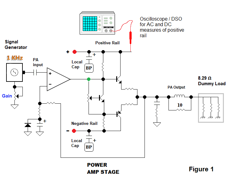
 Power Amp Stage Notes:


Section A   The Final Amp | 21 Watt power amplifier for clean jazz guitar.

Above — Schematic of the final power amplifier developed for this series. Much of the design keeps the VAS + VBE multiplier, and ultimately the final output pair from instant destruction when things go wrong. For example, a speaker disconnection, or accidental bench experiment electrical short.  Of course,  we likely can't provide fail proof protection to sustained adverse events.

This amp includes an abundance of medium power transistors: BD139 | BD140 , plus current limiting in the VAS + the final drivers.

Most resistors outside of the input differential pair circuitry are 1/2 watt rated.  Most caps are 50 VDC rated.  In the schematic above, I've got the 1000 µF filter capacitors going to signal ground for clarity. Actually, they return to their own special ground @ the power supply as discussed in Part 1.

Above — 12-bit FFT of the maximum clean signal output | 21 Watts. With a beefier power supply , ( such as +/- 30 to 40 VDC on the rails),  better heat sinks on the power follower, and slight adjustment of the 2 current source emitter resistors, this amp could work OK to <=50 Watts or so.

On the bench, I hooked it to my dummy load.  I applied a 1 KHz tone and drove it to the brink of distortion as described in here on my Dummy Load page. That's what you see in this FFT.


Above — PA board installed in the amp.


Above 2 photos — In chassis for testing.  I'm using some of the installed rear panel jacks as temporary paths for input into the PA. This allows PA testing and real-world tests of the preamp + tone shaping stages.  2 speaker output jacks wired in parallel provide output possibilities.

I'll go through some notes:

I build circuits from DC to ~ 1.5 GHz on FR4 board using Ugly Construction. Evidently, this frightens some of my readers.
 

Board Construction & Heat Sinking

I built the PA on 2-sided , 1 ounce copper clad board. Circuit paths, or islands were carved with a motorized tool while outdoors. I also isolated each  board mounting hole so the board does not get connected to chassis ground when bolted in. I seek star grounding for each circuit board.

The PA board gets lifted off the chassis by spacers that prevent shorting the power BJT mounting bolts to the chassis [ recall that they're connected to each collector terminal]. This also allows air flow under the PA board for cooling.


Above —Heat sinking the power followers. I bent ~ 20 gauge aluminum with a brake to fashion crude heat sinks. Further, under each heat sink lies a small piece of 24 gauge copper sheeting and under that lies more 24 gauge aluminum stock.

The copper sheeting + aluminum heat sink is secured to the main board with the main power transistor mounting bolt plus an additional 6-32 bolt below each transistor. The additional bolt presses the heat sink & sheets  firmly onto the main board  — and lowered BJT temperature 3-4 degrees C more than without the extra bolt during tests.

For my 21 W amp, this crude heat sinking worked OK for this, my first solid-state guitar amp.  In a test setup with a dummy load, I applied a 1 KHz signal to give 20 Watts output in the DSO & left it that way for 24 minutes ( a torture test ). The big NPN measured 47-49 degrees, while its PNP sister measured 54- 56 degrees C.  My heat sink resistors measured 82 degrees C . When playing guitar at a comfortably loud bedroom volume, the transistors run around 23-24 degrees C.

Transistors

For the small signal transistors, I call for the MPSA06 and MPSA56 BJTs, however, by this time, I'd run out of them and applied 2N4401/2N4403.  My experiments showed that the MPSA series transistors  are better matched from BJT to BJT and likely prove a better choice for the differential input pair at least.

While I chose the very husky MLJ21194 +  MLJ21193 as power followers, a 2SA1302  2SC3281 pair, or even the TIP 35C | 36C could work well.  All of my parts were brand name & purchased from reputable American dealers. I saw a couple of cheap bootleg transistors let their smoke out during my several PA builds under heavier current.

In previous versions of this amp,I employed T0-92 encased transistors for all but the finals and the BD139-140 BJTs in earlier versions of this amplifier. This proved a big mistake. With mishaps + during torture tests,  the VAS transistor quickly or progressively failed  and the VBE multiplier died instantly. This led to a current surge and caused the fuses on my AC transformer secondary side to blow.

While T0-92 transistors provided a lovely high Beta, they led to a lot of frustration. In audio amps, and in particular guitar amps, "overbuilding" seems important. Thus, I used a lot of medium power transistors — even for the current sources.

Current Sources

For my build, I ran out of BD140s, so I bolted two TIP42A's onto my circuit for the current sources transistors. I isolated their mounting points and also sought them for mechanical rigidity — a needed thing when you build using Ugly Construction. The current sources exhibited nearly 0 temperature drift once they ran for ~ 1 minute.

I closely measured them in a variety of situations and placed some of this data in Table 1 on the schematic.  The input pair get sourced with a lovely high impedance with a current that varies from 6.25 mA to 5.7 under test conditions. I sought around 10 mA for the VAS supply , and measured a range from 10.5 to 8.61 mA with the amp driven to a constant 3W, 5W , 10W and 20 W output. 

This shows what happens to my DC power supply under different amplifier power loads.  I placed in DC measures in Table 2 below:


Since I'm only going with  1 pair of finals, the VAS current needs to be high enough to fully drive the top half of the AC signal swing @ high output to a potentially low output impedance . For example, with two 8 Ω  speakers in parallel which doubles the current needed to drive a single 8 Ω speaker.  The emitter follower located before the VAS helps that cause immensely.

Ultimately, For lower current, distortion, heat sinking requirements and  DC ripple, I plan to stick to an 8 Ω load, however, i plan to experiment with different speakers and all of mine are currently  8 Ω speakers. If  I find 2 speakers I like better together than just a single 8 Ω unit, then I'll order these 2 speakers in 16 Ω for a final future amp.

Amplifier Topology

A basic 3 stage power amp that borrows heavily from the recommendations of Douglas Self. The classic differential transconductance pair serves as the input stage to subtract negative feedback from the input and drive an error voltage to the voltage-amplifier stage or VAS.

In professional power amps, input differential stage emitter + collector resistors get replaced with high Z current sources + mirrors.  Discrete transistor current mirrors improve the balance of the input pair across a wide frequency spectrum to cancel the 2nd harmonic. You'll see a variety of current mirrors used extensively within op-amps to boost linearity & reduce HF distortion.

Some designers employ boot-strapped resistors to supply the VAS current and this evidently can also work very well. I went with a current source.

The voltage-amplifier stage [ VAS ]  provides all the voltage gain in a solid state power amp. I applied Douglas Self's recommendation of driving the VAS with an emitter follower to reduce distortion and garner more current drive for the followers. 

The VAS circuit also contains 2 small COG or NP0 ceramic RF caps to stop HF oscillations. The current limiting transistor helps protects the VAS in event of a catastrophe.

When I first built the amp,  I did not connect the final power transistor collector nor base node wires. Every other part was wired in however. Thus I had a small functional amp to test and measure with a signal generator, DMM,  DSO or oscilloscope, plus a dummy load.


Above — Output of the amplifier with just the BD139-140 drivers in-situ with a +/-15 volt DC supply.  I first test any PA circuit with my +/- 15 VDC bench supply before going to higher DC voltages.

You won't get much power with the 100 Ω degenerative emitter resistors, but can fully test the amp without a lot of current flowing.  By tweaking the 1K pot on the VBE multiplier, I also set the bias across points a and b at 1.2 VDC with no input AC signal applied.  Thus the bias is at a good starting point for when you connect the power followers.

Finally, connect the power followers and adjust the bias while looking at the output in a scope or DSO plus FFT.  The quiescent current of the entire PA ran ~ 22.4 mA.  At full clean signal power it will consume around 714 mA if you connect an ammeter between the supply and 1 of the DC rails.

Of negative feedback, folklore and tribalism

This design applies mixed mode negative feedback: voltage and current negative feedback. Both provide series feedback to provide the same function --  to boost PA linearity.

Negative feedback also affects an amps gain, bandwidth and frequency response, plus its input and output impedance (Z). Negative current or voltage feedback affect linearity + gain similarly, but with respect to output impedance, current feedback increases output Z by the size of the feedback factor, while voltage feedback decreases output Z by the feedback factor. To calculate the feedback factor for each type, a different equation gets applied and I won't go into the math.

A classic HiFi solid state amp with just voltage feedback exhibits a very low output Z that is just fractions of an ohm.  Delivered power decreases as the speaker Z rises.

For decades, solid state guitar power amp designers have applied current plus voltage negative feedback. This leads some to suggest that the solid state amp is now behaving more like a transformer-coupled tube amp that offers a higher output Z  while exhibiting a lower dampening factor. 
Some engineers who design audio amplifiers hotly debate current versus voltage source drive. See this brief EDN article by Esa Meriläinen who argues for driving speakers with current rather than a voltage source. I've got papers by respected authors who state the opposite.  I'll stay out of this debate.

In my PA,  output current is sensed by measuring the voltage drop across a 0.22 Ω resistor in series with the output voice coil. This resistor senses a fraction of the output signal and feedbacks a small voltage to the input stage that is phase inverted and thus "negative feedback".  The voltage drop across the 0.22 Ω resistor goes up or down proportionally to the output current. This variable voltage is fed to the 510 Ω emitter resistor in the 2nd half of the input differential pair, As the fed back voltage increases, amplifier gain decreases. E.g. increased voice coil current increases the voltage drop across the current sense resistor and this bucks the amplifiers input signal.

The 10K resistor connecting the power follower collectors to 1/2 of the differential pair's base node provides the voltage feedback.

Output Impedance and Dampening Factor

Going back to your electronics training, for example -- studying linear power supplies.  In current feedback, the circuit attempts to keep the output current constant meaning that the output impedance has to be high.  For output voltage to be constant the output impedance has to be low. Regardless, whether constant voltage, or constant current, the power delivered is still a function of speaker impedance versus frequency.

Dampening factor is another term that may polarize some guitar amp lovers; especially by those who adore distortion. Dampening factor (aka dampening) = the ratio of loaded Z ( typically 16, 8, 4 Ω ) to the amplifier's output impedance. In guitar world, higher dampening is often considered a bad thing by the cognoscenti. A very low output Z solid state amp dampens the speaker more than a higher impedance transformer-coupled amplifier. This is true according to the arithmetic.

Raising the amplifiers output Z reduces dampening, however, the most significant factor affecting dampening is the series resistance of the speaker voice coil. I once significantly changed the dampening on a friend's solid state amplifier with no soldering — I put in a different speaker with a much lower voice coil DC resistance. He loved the result.

How I chose the 820 Ω feedback resistor.      Color you PA Tone

The other board bolted in the amp chassis thus far contains a split-supply voltage regulator for the op-amps used in the preamp and tone shaping circuits, plus this board also houses the first preamp & it's connected to a 1K gain pot.

I connected my guitar to the amp input and routed the output of the first preamp into the power amp input. It's interesting to listen to a guitar amp with no tone control circuit -- and just 1 volume control.

I connected an 8 Ω 12 inch Jensen speaker to the amp and played through it. Instead of the 820 ohm resistor, I place a 1K 2 Watt potentiometer in the feedback loop and tweaked the pot as I played.

I seemed to hear some changes in the bass & treble frequencies at different rotations of the pot. This aurally supports the claim that current feedback tends to boost lows and highs and thus provides a mid frequency scoop. Further, I seemed to prefer 1 particular setting on the pot.  I removed the pot and measured it with an ohm meter.

Continuing on, I tried 4 other 8 Ω speakers that I had on hand at the moment. I also tried different speakers in parallel.  In most cases, the setting on the pot that I seemed to prefer was different.  I also tried longer speaker wires  ( 16 foot, 8 foot versus 3 foot  ) -- this exhibited a small effect on 2 of the speakers but this in turn felt dependent on the pot setting.  Speaker cable resistance can potentially exhibit an effect on dampening in a very low output Z power amp.  Normally, I use a 3  foot ( 91 cm) speaker cable

The 1 pot setting that worked as a compromise setting was then determined: 811 Ω, I soldered in a 820 Ω 1 Watt resistor in for now. When I finally complete the amp and decide which speaker(s) to use, I'll repeat my test with a potentiometer.

The current feedback resistor allows for a potential change in the output impedance that can allow for some equalization of the speaker - power amp system in concert with the speakers frequency response + resonant frequency [ speaker resonance often lies somewhere between 75 - 120 Hz and varies from model to model ].  I wonder if adjusting the pot allows you to enhance the resonant frequency of the speaker?

This function paled in comparison to actually changing the speaker. Using speaker choice to dial in whatever desired guitar sound lurks in your head seems critical. Then you can try to tweak it with a current feedback resistor choice.


Section  B   Faux Amp


Above —  Schematic for a faux amplifier I built for plus and minus 15 volts all on 1 PC board to investigate PA stages, plus different preamplifer circuits.  Clean signal output = 9.5 Watts, as my bench split supply has a small transformer and normally gets used for developing small signal op-amp circuitry. This was my first split supply power amp and I learned a ton and gained some confidence.


Above — The finals were mounted directly on 2-side copper clad board. At under 10 W power, they did not get above 30C even during maximum power torture tests for 15-20 minute stints.


Above —  RCA inputs used for connecting the +/- 15 volt split DC supply to this board. This is OK for a low power experimenter board, or for op-amp circuitry, but not recommended for real power amplifiers.


 Above —  Entire board. In the forefront lies an RCA jack connected to the PA input.

Above —  FFT with maximum clean signal. Above this drive my power supply voltage sagged excessively and distortion increased exponentially.


Above — Time domain. Compared to above,  increasing the drive by 1 Vpp produces harsh clipping.


Above — I've connected a preamplifer module to the power amp. I'll cover several preamp schematics plus discussion in Part 3 of this series.


Above — Side view. You can see the power supply rails. Generally you want to keep them closer together, but this was my first go and gave me lots of building space.


Above — Output section. The emitters connect to their resistors through small holes. I wound the coil and held it together with tape. This OK for a temporary project. I connected the output jack to either my dummy load or speaker(s).

I enjoyed this little amp and it sounded great. Surprisingly, a 9.5W amp cranked up proves quite loud in an electronic lab.

Miscellany


Above — This power amp featured parallel power followers to reduce current-induced Beta drop when driving 4 Ω loads into 60 W. I learned from this board that the most important stage in your entire amp = the power supply.

To get desired a output power, your DC supply needs to provide the needed current without sagging too much under full load. Using transistors that are specified to have lower Beta drop, plus putting them in parallel does help the Beta drop issue. The BJTs = MLJ21194 & MLJ 21193. Heat sinking was provided by copper plating on the back side to the board.


Friday 1 November 2019

Signal Generator for Bat Receivers


Introduction


In summer months, around dusk, I venture into our garden to watch bats feast on flying insects. In my valley, bat research + conservation garners deserved attention.  Bats prove an important part of nocturnal insect control & also help cycle nutrients from wetlands into forests.
Bat detectors, or bat receivers input bat audio in the range of ~15 -120 kHz and output AF into head phones, and/or give a Fourier transform of the received waveform on a small screen, or, in some cases, also provide the bats vocalized frequency range.

Bats frequency modulate ultrasonic audio and rapidly sense the location of fixed and/or moving objects in 3-dimensional space as they fly.  I’ve watched bats sense and careen around my dipole antenna wires on many occasions. They amaze me.

Bat receivers seem to fall into 3 basic categories:

  • Direct conversion; also call heterodyne, or zero IF
  • Direct digital sampling
  • Down conversion using logic IC division to move the frequency into a spectrum humans can hear


I plan to design and build my own bat receiver and to be honest, this task seems fairly unremarkable for someone who on occasion, designs and builds radio equipment. What you might lack is test equipment.

In order to start, I sought, an ultrasonic signal generator to help me design front ends, test mixers, and so forth. I wanted a very temperature stable signal source that gave some outputs between 15 to 100 KHz.  I sought a reasonably low distortion sine wave signal into a well buffered output network with amplitude control.  I require a sine wave output to measure loss or gain in my filters, amplifiers and downconverters.

Main Circuit Schematics 
Above — Main oscillator with binary division + signal conditioning.

The 74HC4060 14-stage ripple counter seems delightful. It offers a number of flip-flop bit counters, plus an inverter so you can hang an oscillator off this IC.  For temperature stability and ease, I chose a crystal oscillator. I wanted an output of 200 KHz, so that gave many crystal choices — ultimately, I went with a 3.2 MHz crystal fashioned in the usual Pierce oscillator topology.  Selecting output Q3 with Pin 7 gave divide by 16 and a 200 KHz output.


Above — Inverter output of my 4060 clocked at 3.2 MHz.

The 74HC193 4-bit synchronous binary up or down counter takes the 200 KHz signal and further divides it according to the 4-bit WORD set by data input pins 9, 10, 1 and 15.  Pin 9 is soldered to ground and stays Low. Pins 10, 1 and 15 are preset High through the 22K resistors. Thus the function table shown in the schematic should technically have Low placed in front of the other bits. For example, divide by 7 = Low, High ,High, High.

Pins 10,1 and 15 are set low as required by turning on a MOSFET switch. The 2N7000 is a lovely, inexpensive way to ground lower current components. I measured the average ON resistance on my board at 3.2 Ω for my 2N7000 trio.

A front panel switch controls the data bits of the 74HC193. You could eliminate the front panel 7PST switch + FETS and just ply 3 SPST front panel switches, however, I prefer grounding data pins local to the counter IC  — and not having to remember switch combinations to set the bits.

Steering diodes keep the MOSFETs on or off as selected. Not all of them are technically needed, but they cost pennies and ensure stable performance.


Above — Output of divide by 2 from the 74HC193 synchronous 4-bit binary up/down counter.

Following the programmable counters, comes a 74HC74 D flip-flop. Nothing cleans up a digital pulse better than a flip-flop. As you switch through the 7 frequency channels, each output exhibits a 50% duty cycle and is well conditioned for low-pass filtration into a sine wave.

Onto the low-pass filters and buffer stage:


Above — My low pass filter banks + the AF gain control and output buffer.

All signal capacitors are polyester types such as  polyester film, or metallised film etc..
I employed the NE5532 op amp throughout.  The 1  µF input connects the signal to a single order low-pass pole set for around 100 KHz and then into a unity gain buffer.

All of the op-amps employ a gain of 1 which simplifies construction.  The signal then passes through a cascade of second order low-pass filters that employ a Q of just under 1 ; Sallen-Key topology; and a Chebyshev response with a maximum ripple of 1 dB.

All filters use the same capacitor values and you can see how changing the 2 resistor values affects the 3 dB response of each filter.  I chose 5 filter outputs. The 20 + 25 KHz filter and 14.3 + 16.6 KHz  get combined to save 1 op-amp + 4 capacitors + 5 resistors.  Since these frequencies are fairly close together, attenuation of the higher of the 2 frequencies is minimal. You could actually make the whole board with just 3 filters: 50, 20 and 14.3 KHz, however, attenuation of some frequencies could be a deal breaker dependent on your needs.

The worst filtration occurs at 100 KHz, where the 2nd harmonic is only 20 dB down. For me, that's OK since I don't plan to use this much and its still reasonable for measurement purposes.


Above — The 100 KHz signal in Time Domain.


Above — An FFT of the 20 KHz signal. The worst harmonic = 38 dB down from the fundamental tone.  In an FFT of the 14.3 output, the worst harmonic is 43 dB down. Good results from simple low Q,  low-pass filters with 10% parts.
 

Above — A Time Domain DSO capture of the 20 KHz signal.

The various filter outputs connect to a 5 pole switch ( I stock 7 pole switches so 2 lugs go unused).
I can select the appropriate low-pass filter and may even "double down" by using the next  lower frequency filter knowing that the signal will get attenuated.

A 1 K pot allows a range of outputs from down a maximum somewhere between 5 and 7 volts peak to peak down to  ~ 10 - 20 mV pk-pk.

The output passes through 1 more unity gain voltage follower then to an AC-coupled RCA jack.
I plan to drive circuits directly,  or connect a piezo-electric transducer, or a MEMS ultrasonic transducer (CMUT) as needed.

Photographs and Final Notes


Above — I designed this project on the bench and built it using Ugly Construction.  I added  a power on LED to the circuit.


Above — Photo of the 7 channel selector switch plus entire circuit board. I do not plan to put in a case. I'll use it like this over the next couple of years.


Above — Filter section knob, plus gain pot and output RCA jack. I'll trim off the unused copper board using aviation shears.


 Above — Unused filters designed for 16.6 and 25 KHz.

Friday 4 January 2019

Clean Jazz Guitar Amp Builder Notes — Part 1: DC Power Supply


— D I S C L A I M E R —

The text, diagrams and images on this blog are presented for information purposes only.  You are entirely responsible for any damages, harm, or injuries that arise from any equipment you build, or from any experiments you perform.  —  Experiment and build at your own risk —

Building a power supply & audio frequency equipment poses a serious risk of personal injury, death, destruction of personal property and for fire. Safety first !  Always keep children and pets away from your bench. 

Further, all home built equipment should never be connected to your household Mains AC electric system when not in use. Connect your AC power supply containing devices to a suitably rated, commercial switched power bar, or switch system that is certified/approved in your Country. For example by the CSA Group, ANSI, ASME, ASSE, ASTM, ASFE, UL, NSF etc..  Turn your device AC supply on and off with this power bar/ switch system —  or better yet, unplug it when it's not in use, or unattended.   

Work safely!  Prevent accidents and fires.  Keep an annually certified fire extinguisher in your home shop, or lab at all times in case a fire starts.

Above — The fire extinguisher that hangs in my lab. We also have 2 others: 1 next to the electric clothes dryer & 1 in the kitchen. According to local fire officials, these 3 places are the most likely areas for a fire to start in a non-smoking home.

A. Basic  Power Supply Goals

[1] Electrical safety.
[2] Low ripple.
[3] No amplifier hum, or noise caused by ground loops, or inductively and/or capacitively coupled rectifier pulsations.
[4] Manage heat and/or prevent expensive component damage from thermal runaway, or a catastrophic parts or design failure.

I'll show my pursuit of a split DC supply for a jazz guitar amplifier [ ~22-24 Watts into an 8  Ω load ].  I learned a ton making this power supply, and, of course, this knowledge will boost the success of obtaining the above 4 goals in future designs.

B. Transformers 

In 2018, I bought 2 suitable iron transformers: a toroidal + conventional frame type. Likely, the transformer is the most important plus costly object in your whole amplifier build.

This blog will lean towards low power clean jazz guitar amps, however, all the same principles apply for higher power guitar amps.
I show how I measure my amplifier power ratings near the bottom of  this blog page:  Click here


Above 2 photos — My 2 transformers.  I purchased the "Torel" toroidal unit on eBay from hansurmann from the Russian Federation.  I purchased the Hammond 'heavy weight' locally & mainly because I got a very good deal on it.  The heavy Hammond transformer will either go in a lab power supply, or perhaps a combo amp that never leaves the lab.  It's a well built transformer that offers separate bobbins for the 2 windings eliminating the need for an electrostatic shield between the primary and secondary coils.

Hammond Manufacturing also offers a good selection of Toroidal transformers to view and to learn more about them.  Click here.

Transformer power rating isn't usually expressed in Watts; rather VA (Volts [RMS] and Ampere units). So my Hammond center-tapped transformer as shown is 30 VAC * 5 Amps = 150VA. This would work very well for a 4 ohm load guitar amp.

Your transformer's secondary AC voltage and rectified DC voltage varies with the diode type + rectifier topology, how you filter the pulsating DC into low-ripple DC voltage  — and the load on the power supply .  If you seek to make a 'specific' wattage guitar amp, this makes choosing your transformer output AC voltages a little more difficult than you might like.

Hammond Manufacturing offers a file with some math and rectifier circuits to make this job a little easier:  Click here

For a ~22 Watt 8 Ω jazz guitar amp. You'll roughly need +/- 23 to 24 volts on your power amp stage DC rails (under heavy load) to get that maximum clean power.
For this project, I do not regulate the DC supply going to the final power amplifier.  Only the pre-amplifier stage op-amps get regulated DC.  I think this is typical for guitar amplifier power stages.  Unregulated DC on your PA rails offers a proven, reliable strategy, and of course, gives lower cost & complexity than when you put high power linear regulators on the power amp stage DC supply.

Unregulated, you won't achieve the somewhat theoretical doubling of maximum amplifier power when going from an 8 to 4 Ω load, since the current draw doubles and this results in a greater voltage drop in the DC supply system.  This also may occur because of AC signal factors: mainly increased PA transistor beta drop which I'll discuss in Part 2.  As aforementioned, you need to consider many factors when choosing what DC rail voltages you'll need to get a certain clean signal amplifier power.

When driving our PA stage, we suffer DC power losses from many factors. These include transformer winding resistance and leakage reactance, I squared R energy losses in your power supply system wires + any resistors including PA emitter degeneration resistors and so forth.

Above — A simple bench setup to measure AC + DC voltages on either of the DC supply rails. I'll use this to measure my positive DC rail voltages -- and later,  peak-peak voltages [ AC ripple voltages ] on the positive rail.

Above — DC measure of the positive rail of my power supply that's connected as shown in Figure 1.  The signal generator is switched off, or to 0 output.  The unloaded positive rail measures + 27.1 VDC.

Above — DC measure of the power supply when connected to a PA driven to maximum clean signal power [ 23W ] by the 1 KHz signal generator.
The unregulated positive rail has sagged to 23.1 VDC under this heavy load.  We'll use the above measure when we calculate % ripple in Section E. Reservoir Capacitors and Ripple.

You can't just casually order a transformer like you would some power resistors. Also, the cost may shock you; especially if you live in Canada.  Making a power supply takes some thought & planning.  Think about your transformer's VA, weight, mounting requirements, RMS AC output voltage, what maximum peak - peak signal voltage, you seek, plus other factors such as whether or not you plan to put the power supply right on the amp chassis, or sit it on the floor of a combo amp with patch wires connecting the power supply to DC power rails.

As you go up in amplifier power rating & apply bigger transformers that provide a larger split DC voltage with more current, your build increases in difficulty. Heat sinking requirements,   I squared R losses, the need for thermal protection/current limitation circuitry -- and the potential for unwanted noises all go up.  This is especially true if you wish to drive a 4 Ω load.

No one showed me how to make a solid state guitar amplifier, that's why my blog needs to be taken with a grain of salt.  Experts and critics may just lurk and smirk —  however, I welcome constructive criticism from any readers who know more than I.  We all learn that way.

That's why I chose a  roughly 23W into 8 Ω clean guitar amp for my first build. Keeping the power down hopefully will allow us to enjoy success in order build confidence, plus gain the skills we might apply to future higher power amps if so desired.
  
C.  Schematic

Above — Power supply schematic. For this project, I used the center-tapped Torel toroidal transformer that was listed as 50VA with + 18, 0,  and -18 VAC RMS output.  Mine measured 20 VAC peak -- and rectified + filtered under load, I get a nominal +/- 25 VDC output.  The panel mounted fuse is connected to the hot polarized AC Mains plug.  This power supply gets used in all experiments shown on this blog page.

Above — Measuring the positive DC rail with no load on a DVM.  I built my power supply enclosure from 2 - sided copper clad board.  The lid is off for testing and photography.  Although toroidal transformers leak less magnetic flux than conventional frame types, they still require electrostatic shielding to prevent capacitive coupling to nearby circuitry.  Sometimes moving or rotating them may reduce their hum field.  In general, keep you power supply away from your signal path circuitry; and especially your pre-amplifier.

If you consider the wires that lead to and from the transformer, the rectifier diodes and the reservoir capacitors as a loop — the smaller the loop area, the better for EMI prevention.  A loop potentially may inductively couple the transformer pulse currents into your nearby circuitry causing an annoying background AF buzzing noise that cannot be filtered off with bypass capacitors.

I'll go through the circuit starting with the Mains AC supply.

Years ago — for anything I make that uses AC mains electricity.  I switched to only using an IEC320 C14 receptacle — plus a cord containing an IEC320 C13 appliance plug on 1 end, and a grounded NEMA 5-15P polarized plug at the other  Since they're commonly used on personal computers in North America,  you seemingly can always find a cord if you forget or misplace one.


Above — Another view of the power supply with the cover off.  The IEC320 C14 receptacle contains a 10 amp DPDT switch.  The 2-sided copper board is well soldered on both sides so it's technically RF tight around the transformer and mechanically solid to strongly support the AC  receptacle and fuse.


Above — The IEC320 C14 receptacle with DPDT switch & the toroidal transformer mounting hardware.

D.  In Rush Current

When you turn on and energize a power transformer, an instantaneous surge of current gets drawn to charge up the reservoir caps and to magnetize the transformer.  The magnitude of the in rush current is not related to the amplifier load, rather it's dependent on the point in the Mains AC wave cycle when the transformer is switched on.

On the (low resistance) primary coil side this puts potential strain on your switch and fuse -- some larger toroidal transformers will even snap off a house circuit breaker the odd time.  Thus ensure you use a slow blow panel fuse, plus a well rated switch.  For example, I used a 10 amp @120 VAC rated switch.  Perhaps overkill for a small guitar amp, but you get the picture.

On the transformer secondary coil side, your rectifier diodes and reservoir caps get strained during any start up surge.  Any rectifier diodes must be tough.  I initially purchased a commercial 25 Amp rated diode ring that featured a heat sink and mounting hole. Sadly, this part tested defective. I looked in my rectifier parts drawer and saw about 40 Vishay brand 1N5822 3A Schottky barrier rectifier diodes and then studied their datasheet online. These should well handle my voltage, current needs and any brief inrush surge. They work well for my particular guitar amp. I have no idea when, or who I bought them from however.

I put a slow-blow fuse on each AC secondary to keep the transformer alive should the diode ring ever go shunt to ground.  Currently, I've got a 2 Amp slow blow fuse in each slot. The X capacitors are to bypass any HF noise created by the switching diodes from going into the house wiring.
I used hulky capacitors because in the presence of AC bias, some small size ceramic caps may not hold their capacitance value.  These 1 kV caps are cheap and easy to find. Carefully check the datasheets for any parts you place in your power supply and consider avoiding 'no - name' parts.  It's really sad when you fry a $50 transformer because you decided to save 50 cents by plying a, cheap no-name, part.


Above — The improvised diode ring.  I'll shorten the wires even more.  Sadly, I misplaced my 0.01 µF/ 1kV  X capacitors and had to order more. No doubt, I'll locate them the day the fresh capacitors arrive.  I'll shorten the diode ring wires when I install those X capacitors.

E. Reservoir Capacitors and Ripple

The main question we all ask — how big should my reservoir capacitors be?  Professor Ken Kuhn wrote a great pdf document for his students.  Click here

I consider this document essential reading.  Also check out his fantastic web site.

Some audiophiles get carried away with 'requiring" ultra low ripple at high power.  From Ken's article, consider aiming for medium to low ripple and use the smallest capacitance that will achieve that goal.  Higher capacitance increase surge current as Ken mentioned in his article. More capacitor = more dollars too!

Ripple is a nuanced number that's conditional and contextual. DC supply ripple increases in tandem with PA stage current draw. So ripple could be quoted with no power supply load, with the amp at 1/2 power, full power and so on.  For a clean jazz guitar amplifier, the best case seems to be with no applied test signal and the worst case occurs when you apply the maximum test signal before the amplifier sine wave distorts. This is often quoted as the maximum signal drive where amplifier THD is under 1%.

On the web, you'll find a number of write ups and videos how to calculate percent ripple, or, the reservoir capacitor value you need to get a certain percentage ripple. Sometimes they lack precision and seem a bit theoretical. We amp builders need a practical, measurement-based way to evaluate ripple.  I'll show some simple oscilloscope measurements and apply Professor Kuhn's formula below.  It seems to work OK.  It's also fun to actually view the ripple on your DC rails with various reservoir capacitor values and power supply loads. Visceral stuff.

Above —  The formula taken from Professor Kuhn's document.  To get data to calculate, you'll need a power supply, a signal generator, a PA stage, a dummy load and a oscilloscope or DSO. I've already shown how to measure rail DC with a 'scope DC coupled to your rail earlier in Figure 1.   Again, I'll only show the positive rail.

I place additional ripple filtration capacitors on both my pre-amplifier and PA boards. We'll only consider the PA board.  As shown in my power supply schematic, my main reservoir caps are 6800 µF.  On my PA board lie additional capacitors and on my test 23 W power amplifier,  I've got a 2200 µF /50 volt electrolytic capacitor on each of the DC supply rails.  So per rail, that's a total of 9000 µF.

Above — DSO screen capture with an AC coupled 10X probe on the positive rail with no applied signal drive. This would be the "best case ripple", but seems totally unrealistic as the PA is drawing only 16 - 20 mA quiescent PA bias current from the power supply.

Above — A DSO capture of the AC signal on my positive DC rail using an AC-coupled 10X probe. The V peak-peak = 660 mV.   This is 'worst case' ripple as my PA is drawing maximum current; a heavy load for the DC power supply.

Using Ken's formula, let's calculate the percent ripple from the data we've gleaned.

Ripple = 100 *  RMS Ripple Voltage / Average DC Voltage

Your DSO may calculate and display the RMS ripple voltage, however, let's assume you've got a 25 year old oscilloscope with no math functions.  We might simply just estimate RMS ripple voltage by taking the measured V peak-peak value and dividing it by 3.  We bring the 'worst case' DC voltage from the earlier DC measurement of the positive PA rail.

Ripple = 100 * (0.66 / 3) / 23.1 = 0.952%.

On a popular (but unnamed) jazz guitar amp I recently measured,  the AC ripple signal was around 2 V peak-peak with maximum clean drive signal into a 8 Ω resistive load. So I did OK.

This simple method allows you to measure and crudely calculate ripple percentage to make comparisons with different capacitors in real time.  So my 9000 µF of C in a low-power jazz guitar amp ranks as ultra-low ripple at 'worst case'.  Of course, if you go for a 4 Ω load, it could be a game changer.  More on that in Part 2 of this series.


Above — My 2 main reservoir capacitors.  Installing them proved a little time consuming. I built my power supply using Ugly Construction on 2-side copper clad board. Since you can only solder their short, thick leads on the bottom side of the main circuit board, I had to improvise.  I cut Cu islands for the DC rails and O volt pathways on the top side.

I also had to cut islands on the bottom side of the Cu board.  I connected the positive, negative and 0V top islands to their respective capacitor leads below by joining the top and bottom carved islands with via wires. I drilled 5 via holes for each lead and soldered 20 gauge solid copper wire to join each appropriate top and bottom island. I'm used to doing this to provide a low impedance ground in UHF circuits, so it's not a big deal for me. After final testing with an ohmmeter, the 6800 µF caps were installed. I did the soldering with my 80W iron.

I installed the filter capacitors by drilling 1 hole for each cap lead into each of appropriate carved islands and then soldered each capacitor lead to the bottom copper board.

F:  Power Supply, Signal and Filter Capacitor Grounding Scheme

We ought to consider ground loop hum and reduce it by carefully placing our parts, rails and various types of ground wires to avoid contaminating our signal ground with charging currents from filter capacitors and other unwanted AC currents.  You'll also need a scheme to connect your signal ground to chassis ground plus Earth.

A stellar reference for this topic and also my entire project = 
Audio Power Amplifier Design by Douglas Self .  I can't recommend this book enough.  Click for Doug Self's web site

Doug Self's practical knowledge, writing skills and published experiment results provide game-changing insight into the world of audio design from small signal to PA stages. 


Above — Grounding scheme.  We've got multiple ground terms which gets confusing. On the power supply circuit board lies Reservoir Ground.  Reservoir Ground is the 0 volt rail on the power supply and it's only connected to the transformer center tap and 1 node of each reservoir capacitor.  Lots of pulsating charge current flowing here.

Signal, and Electrolytic Capacitor 0 Volt Grounds on any circuit boards are connected to the Reservoir Ground by wires.  I made a tee off the Reservoir Ground rail and put an Electrolytic Capacitor Ground point at 1 end —  and the Signal Ground point at the other end of this tee.

This separates pulsing capacitor charging currents from Signal Ground — and by way of the tee, keeps these 2 points confined away from the 2 main reservoir capacitors.  Connecting Signal Grounds to 1 point on the Reservoir Ground rail by wires is commonly called star grounding.

Apart from the power supply board, most circuit boards will have only Signal Ground, or Electrolytic Capacitor Ground.

Signal Ground on any circuit board gets connected to the Star Point on the power supply board by a wire as shown.

Grind away any copper on the power supply, pre-amplifier, PA or any auxiliary circuit boards that your circuit board anchoring hardware passes through.  This prevents you from connecting any type of circuit board ground to the chassis through any bolts, spacers, washers and nuts used to mount your various boards to the chassis.

In essence, the circuit boards are "floating" from the chassis.  They won't truly be floating since we'll connect these boards to the chassis by a special means that's described later.
Consider the DC rails on the PA and pre-amplifier boards. At the beginning of each positive and negative DC rail lies electrolytic capacitor(s) that connect to a small 0 volt rail (Electrolytic Capacitor Ground) that is separate from the Signal Ground on each board.  On my boards, I carve out a small island for the Electrolytic Capacitor Ground rail. Run a copper wire from each Electrolytic Capacitor Ground island back to it's proper grounding point on the power supply board as shown.

Auxiliary board 0 Volt ground returns such as those that contain relays, thermal, or non-signal support circuitry get connected to the their own special tee to Reservoir Ground on the power supply circuit board by a copper wire.  See the diagram.

Mains ground from now on is called EARTH.  EARTH is the AC ground lug of the IEC320 C14 receptacle. Connect a thick, shielded copper wire from this EARTH lug to the guitar amplifier input jack ground lug.  Thus, the amplifier input is EARTHED by this wire.

The 2 - sided copper clad board surrounding my transformer is also connected to EARTH lug of the IEC320 C14 receptacle.  Since my power supply shielding box is "floating" from the chassis it will only be connected to the chassis by way of the single wire mentioned above.

Signal Ground is connected to Chassis Ground at 1 point.  Some designers do this with a 10 Ω resistor.  For example, you'll see this in the Fender Jazzmaster Ultralight guitar amplifier schematic.

Another way, I learned about from Doug Self,  is through a shielded input cable from the guitar amplifier input jack to the first pre-amplifier stage.

The 1/4 inch guitar amp input jack's grounded sleeve body is usually automatically connected to the metal chassis because it's a conductor.  Check it with an ohmmeter.  If you use a plastic 1/4 inch amp input jack, you'll have to connect its ground lug with a short wire to a bolt on the chassis. Whatever you do, ensure you've got a solid, low impedance connection to the chassis from the amplifier input jack's ground node.

The ground braid or shield of the proximal input coaxial cable gets connected to the guitar input jack ground lug.  However,  recall that the jack ground lug ( and chassis ) is also EARTHED through a wire at exactly this point — providing strong ground loop immunity.

The distal end of the coaxial cable goes to your pre-amplifier input stage. The braid at this end goes to the star grounding point on the power supply circuit board as shown. So you now have connected your EARTH, Chassis and Signal Grounds to the Reservoir Ground in a manner which helps reduce grounds loops.

G.  Regulated DC for Your Pre-Amplifier Board

To garner maximum headroom, it's desirable to run op-amps like the NE5532 and/or TL072 with more DC voltage than the  doldrum standard of +/- 15 VDC.  You might go as high as 17 volts on the rails. Since, I've got an abundance  of 16 volt zener diodes on hand, I opted to build my rail voltage regulators around these. The 17V 1N5247B zener diode might also prove a good choice.

Many builders just run linear regulators and adjust the rail voltages to somewhere between 15 and 17 VDC. 

I chose the field-tested emitter-follower configured DC regulator with a gain of 1.  The base-emitter voltage drop of this topology lays in series with the load, so load current changes will alter the regulator output voltage. Vout = V Zener – VBE:  so the regulated voltage will be under 16 volts if you apply a 16 volt zener diode.  Barring catastrophe, once the pre-amplifier board is connected, the DC voltages on each rail will hold steady.

The BJT base bypass capacitor value gets roughly multiplied by the transistor's current gain which boosts low-pass filtration of the stage to further scrub down rail ripple. The electrolytic capacitor and zener diodes 0V leads go to Electrolytic Capacitor Ground on the power supply board as discussed earlier.
Above — Pre-amplifier voltage regulators: one for each rail.  I added diodes to limit the stage current to a maximum value somewhere above 200 mA.   One diode compensates for the BE junction of the transistor, while the second diode limits the voltage across the emitter resistor to the diode ON voltage ( around 0.6 V ).

I'll show the actual capacitor values + my DC measures on the pre-amplifier boards later in this series of blog posts.


H.  Output Rail Notes
Above — Power Amp Output Rail diagram. This isn't really about the power supply circuitry, however, I don't know where else to put it. Your PA output rail receives all of the amplifier's power and some serious current is flowing here. Authors such as Doug Self recommend that we don't connect our 3 PA output rail networks at the emitter connection points. Make a tee as shown and then choose your 3 takeoff points.  This confines the PA transistor emitter energy away from these 3 nodes.

This is part 1 of a multiple part series about a scratch home brew guitar amp.
 
Part 1 lies here
Part 2 lies here
Part 3 lies here
Part 4 lies here