1. Preamplifer 1
2. Preamplifer 2
I did not get hung up on an ultra-linear signal path, rather tried my best while avoiding the emitter-coupled pairs found in op-amps plus many other analog ICs. It's fun to bias discrete transistors, calculate & measure things like input impedance, or the feedback values needed to get a particular gain and so forth. I miss this stuff. Old school electronics for analog dinosaurs like me.
The Baxandall tone circuitry time constants reflect that T-style guitars generally sound bright. For the classic 100 Hz / 10 KHz Bass + Treble 3 dB turnover tone section, you might wish to run 100 nF and 15 nF for the capacitors respectively. The 50K bass potentiometer works well since I tend to 'pump the bass' & this prevents the impedance from getting too low at the extreme wiper setting seen when when boosting hard.
The treble and bass are fairly independent and the boost / cut is just over 10 dB. Clearly op-amp tone controls boost and cut with more amplitude, but this work OK and proved very simple. The emitter of Q6 provided a convenient node for negative feedback into the tone circuit.
Big thanks Ken! You may change parameters like VBE -- it might be best to measure VBE and input that value, however, if not, the spreadsheet gets you close and offers a great learning tool.
Spreadsheet taken down for re-location to another server.
Above — A screen capture from the spreadsheet manipulated to fit this image file. This shows an example of using the tool to run the calculations for my single DC supply amp shown earlier. Note that the feedback resistor idealized value = 510 Ω, not 560. I adjusted RF using standard resistor values so that the 2 values VC2 center and VC2 actual were as close together as possible -- in this case 0.16 volts.
Above —My actual single DC supply amp with RF = 560 Ω. The difference between VC2 center and VC2 actual is only 0.6 volts, so well within the +/- 2V specified by Ken's spreadsheet. Notice the unloaded voltage gain rose by .91 . In reality my measured voltage gain was 11.7 -- the spreadsheet gets you close. You can manipulate RF and RE1 within reason to target more or less gain. The spreadsheet has a split DC supply example design defaulted into it. Between that example and my single supply examples here, the spreadsheet should prove easy to use if you ever build this feedback amp.
You may also stick a temporary pot for RB1 [ I used a 250K potentiometer] to find the exact center for the Q1 bias on the test bench. With a 1 KHz signal generator and DSO probe on the 22K resistor, I drove the amp just into soft clipping and tweaked the pot to find the sweet spot for a perfect bias voltage. I removed the pot and measured just over 208K. Do not leave a regular potentiometer or trimmer pot in the actual circuit as it may add noise and potential for oscillations.
3. Power Supply
 Above — A basic power supply. The different green and orange LED resistors try to equalize their relative brightness on the front panel. 1 LED for each DC rail.
Above — For the first time ever, I'm using a commercial grade bridge
rectifier and will also apply this part in my high powered amps. You may
heat sink the GBUE2560 for high power amplifiers.
Above — Rectifier and 2 gorgeous reservoir caps for the DC power supply.
Above — The power supply transformer just sitting in the chassis prior to wire shortening and mounting.The Hammond 166L25 gives 12 watts out, while the166L20 gives about 8 watts clean output power. Further, if you regulate the op-amp DC supply with the 166L20, this means running +/-12 volts split as the unregulated DC voltage sags downs to less than 14 VDC on each rail when driven hard.
I also tested a larger transformer with 29 VDC unregulated on each rail & for awhile, Suzu was running at 27 Watts output power. The Hammond 166L25 and 166L20 have identical dimensions. In the end, I opted with the 166L25, since its higher output DC voltage allows running the preamplifier rails at 17-18 volts DC unregulated to get maximum headroom.
Above — The power supply section mounted and tested.
Above — My downstairs Telecaster ™ with a Seymour Duncan Phat Cat single coil pickup in the neck slot and his Alnico 2 Pro™ in the bridge position. I added my newly designed, switchable treble bleed circuit in February 2023.
4. Power Amplifier — P A —
Above — PA schematic. I chose different transistors for the input emitter coupled pair and also for the finals compared to the original GAA -12 Practice Guitar Amp. Further, I sank a little more current in the emitter coupled pair and the VAS/driver stack. At this point, I only plan to run voltage feedback in the global feedback loop, although, I can easily add current feedback if desired.
I
measured a β of 540 for BC546B matched pair. The whole BC54-X- series
seem an incredible BJT collection offering low noise figure plus high β
and, of course, is long obsolete. I've got 30 pieces of the über low NF
BC549 in my parts bins for future 12 volt single-supply, discrete,
low-noise AF amplifiers.
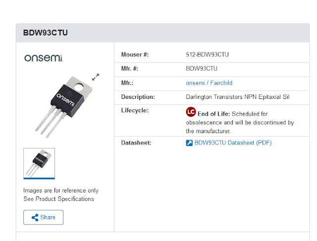
Above — Notice from Mouser. The day after I installed the power Darlington complimentary finals, I got this notice by email. Obsolescence might be the central story of my electronic hobbyist career ? Happily, I've got enough genuine power follower pairs -- both standard and Darlington style to last me for a long time.
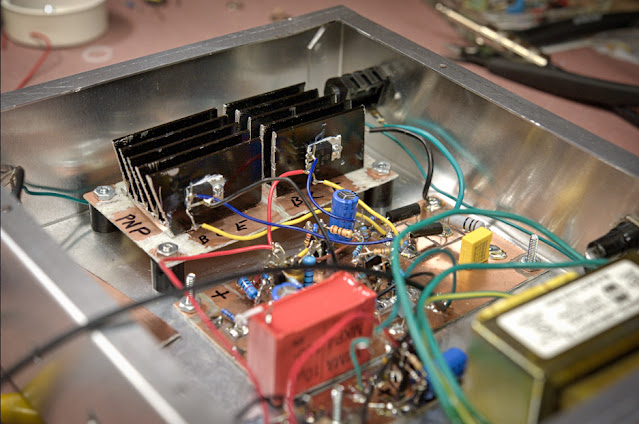
Above —The finals mounted in their heat sinks. Once again a hack saw helped fashion DYI heat sinks.
Above — The finals and PA mounted in the "cake pan". The power
transformer sat unmounted in this photo. Suzu with it smaller chassis and will go upstairs in our living room to serve as my main practice amp. The
downstairs GAA -12 amp serves as my main transcription amplifier. I
spend time downstairs transcribing horn solos. I rarely
listen to guitarists other than if a guitar happened to be on the song of the
horn player whom I'm transcribing. 
Above — Suzu's PA offers low distortion. I'm very happy with this PA stage. The matched input pair have obliterated the 2nd harmonic and I believe what's left are crossover + some intermodulation products from interactions with my outboard circuit, test leads, clips and probes.
5. Speaker
I chose the Eminence Legend 1058 speaker for my upstairs practice amp.
Fortunately, many kind YouTube posters have uploaded head-to-head trials with various 10 inch guitar speakers for comparison. I tend to favour Alnico magnet 10 inch speakers, however, dislike their cost. My "non Alnico" preference seemed to the the Legend 1058 in several videos. So I bought one and found it well suited my purposes. — and the added bonus, it's not expensive.
Above — The large dust cap makes the speaker look bigger than 10 inches in diameter. This speaker is a gem. Ferrite magnet and weighs 2 Kg.
Above — My wife designed & built a prototype cabinet from a plank of 12 inch wide, 3/4 inch thick pine. The final specs are 12 inches depth x 12 inches height x 14 inches width [ or 30.48 cm deep x 30.48 cm height X 35.56 cm width ]. I stuffed some fibreglass pink insulation in the cavity to dampen any reflecting waves. The back is partially open with a 2 inch gap across the top end. This keeps out cats (protects the speaker), keeps in the insulation and gives punchy bass tones with some room audio fill through he back of the speaker cabinet.
Above — I've got a Jensen Mod 10-35 in another identical cabinet at the moment. I like the strong mids for neck pickup solos better when compared to the 1058, however, it sound quite bright. It's best to listen to a speaker for many months before you write in in or off.
6. Miscellaneous Photos
Best regards! Click here for my Guitar-Related Index


