On a whim, I took another look at the LM386-4 one cold Sunday afternoon this November. My focus was to drive a loud speaker and not headphones. I won’t personally use the LM386 for a headphone amp as we enjoy so many better options. For example, an op-amp driving a pair of TO-92 followers, or perhaps placing 2 NE5532 op amps in parallel as the headphone PA stage.
Since the mid 1970’s the LM386 has enjoyed popularity amongst hobbyists for low to flea power AF power amplification. The NE612 mixer IC plus the LM386 have literally formed the basic building blocks of innumerable radio receivers amongst Hams and hobbyists for decades.
Although, imperfect like all other linear ICs, the LM386 design team delivered a simple, flexible, low power AF amp with reasonably low distortion.
This part is noisy though. The input noise density = ~ 50 nV/√(Hz) — about 10X that of an NE5532 op amp. So. if you use this part in high gain mode [with a gain of 100 to 200] and drive it with a low-level audio signal, you’ll really hear the noise (hiss) in your speaker.
Others online have provided detailed analysis about each stage of the LM386, so I won’t bother. However, I will comment about why it might be noisy. Normally, in modern AF power amps. the differential input pair emitters get 50 - 100 ohms of degeneration to boost linearity at the expense of noise. Other than that, in the IC only current sources connect to the emitters (and usually active loads to the collectors -- i.e. no resistors), However, the LM386 input pair get multiple large value resistors connected to their emitters. This translates into lots of Johnson noise from thermal agitation within conductors, plus related high-level input current noise that all gets amplified by the NPN voltage amp and delivered to the output stage.


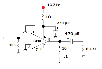
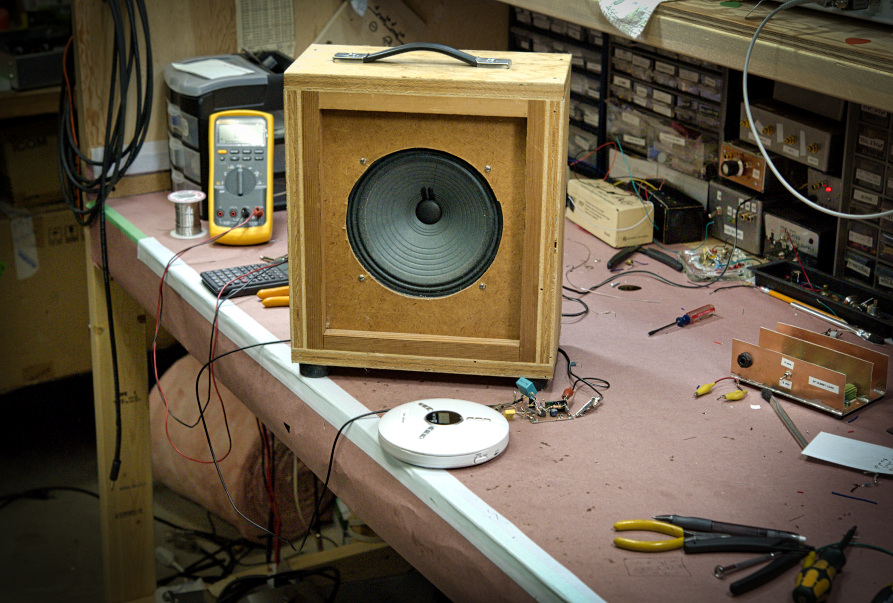
Above — An early photo during my initial bread boarding for these experiments. The non-inverting input resistor was changed to 10K for my experiments.
Index of this blog post
1. Gain = 20 Mode
2. Bass Boost and More
3. Gain = 50 Mode
4. Gain = 200 Mode -- plus lifting and AC bypassing Pin 2
I'm avoiding math in 2022, as data shows that my blog readers don't care for it.

1. Gain = 20 Mode
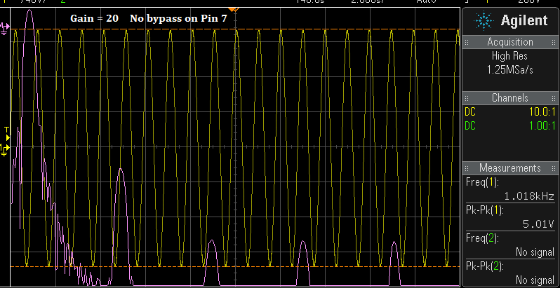


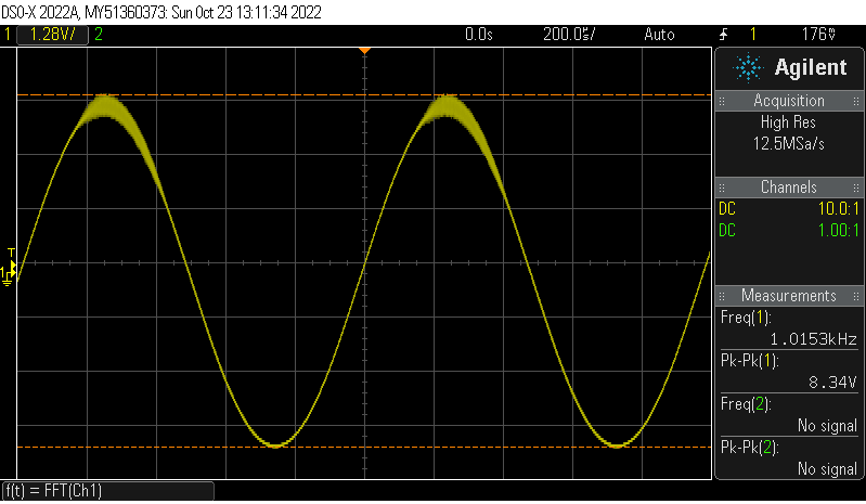
Above — This is the cleanest sine wave I can drive before clipping using my eyeball. This is 725 mW output power.

Above — I kept advancing the gain knob until clipping appeared on the top half.

Above — Switch to FFT mode, although you can still see the yellow coloured sine wave. At this point, the tones are almost level and 45 - 47 dB down. You may easily hear distortion at this level.

Above — I kept advancing the signal generator gain knob until the tones look really strong. You can see the sine wave is now both bottom and top clipped. These FFT screen shots and my notes serve as the basis of what follows. I learned a lot doing these experiments and hope you like them.
2. Bass Boost and More


If you listen to this amplifier with music through a speaker, it sounds muffled and somewhat lacks the important mid frequencies for both voice and music. The hiss is definitely attenuated though. Further, the voltage gain goes from 20 without feedback down to around 8 with the 10K + .033 µF network added. There are other potential side effects to with such heavy feedback which I'll show soon.

Above — FFT with fundamental + 8 tones of the bass boost circuit driven to output 5 Vpp. The feedback has suppressed the 2nd plus all other harmonics effectively. Feedback certainly holds promise in reducing harmonic distortion in the LM386.

Above — The bass boost circuit may produce weird distortion when driven hard in some circuits. The bottom half of the sine wave clips initially.

Above — The FFT of the above DSO tracing when pushed a little harder. This looks and sounds terrible.I do not recommend people use the bass boost circuit, or if you do, please check for instability.
Let's adjust the feedback network and perhaps find something that works better.
In a classic PA with a differential transconductance input pair, 1 BJT base serves as the input stage while the other base receives the negative voltage feedback. The transconductance pair subtracts that negative feedback from the input and passes the difference voltage onto the voltage amplifier stage that follows. This doesn't happen in the LM386 -- negative feedback goes to the non-inverting BJT emitter which is often also the input side of the input emitter coupled pair.
Negative feedback also affects an amps gain, bandwidth, frequency response, plus its input and output impedance (although the output impedance is just fractions of an ohm). When we add AC feedback between pins 1 and 5, our network is in parallel with the 15K resistor and may be affected by other amplifier parameters including the gain and input impedance.
From the data sheet, In low gain mode, we should strive to keep the amplifier's closed loop gain 10 or greater which happens with the 10K resistor in our R C network. It's quite easy to turn your LM386 into an oscillator with too much feedback. I've noticed that feedback networks that look OK in SPICE simulations may actually oscillate in real life bench work -- especially with higher gain and/or drive.
I took the bass boost circuit example, kept the 10K resistor, and tried different capacitor values. If you lower the 10K resistor, you'll have to watch for oscillations at input drive levels high enough to cause distortion. This also may also reduce the LM386 voltage gain considerably.

Above — Our base schematic to evaluate different values of C1 and view the resultant FFT and voltage gain.

Above — FFT at 5 Vpp where C1 = 0.01µF. Outstanding results! This turned out to be the best feedback capacitor of the few I tried. The LM386 voltage gain dropped to just under 11 with that particular capacitor value for C1.

Above — Driving it as little harder to give 623 mW output power. Still fairly clean compared to other tracings.

Above — FFT with the top just starting to clip. 3rd harmonic re-emerging. 735 mW output power.

Above — Pushed a little harder to 761 mW. Things are getting ugly. C1 still = 10 nF. Let's decrease the C1 value by a decade to 1 nF:

Above — FFT at 5 Vpp where C1 = 0.001µF. While not as impressive as when C1 = 10 nF, it's still quite good and the LM386 voltage gain is around 19.

Above — FFT at 7.14 Vpp or 759 mW output power, The second harmonic is somewhat better than the case where C1 = 0.01uF. 
Above — FFT at 5 Vpp where C1 = 470 pF. Another favourable reduction of harmonic distortion when the LM386 amp is running at reasonably high, unclipped power levels. I measured no loss in voltage gain with a 470 pF cap + 10K resistor.
I also tried a 220 pF cap - it worked somewhat, but the harmonic suppression started to fall off at this point. The overall best unclipped harmonic suppression occurred where C1 = 0.01 µF in my experiments, albeit with 45% voltage gain loss.
To decide on a C1 value, it's important to listen to it to with actual audio to ensure that any frequency peaks, or more importantly, the low pass effects caused by the network doesn't wreck the audio you listen to.
Above — Listening to monaural jazz from my CD player into the LM386 and then into my 8 inch lab speaker. Although C1 = 0.01 µF gives the best reduction in harmonic energy, it rolls off too much high frequency audio for my tastes. I usually start at 0.001 µF and work up in capacitance. To my tastes, a 0.0018 or 1.8 nF cap sounded best. We've entered subjective territory. Variables may include personal taste, your hearing + age, your AF signal source overall tone, speaker size -- and perhaps whether the speaker is mounted in a cabinet, etc.. You might consider choosing a feedback cap between 0.01 µF and 470 pF according to your needs and wants.

Above — Listening through my 6 inch lab speaker. My C1 preference = .0039 µF for this speaker.
3. Gain = 50 Mode


Above — FFT at 5 Vpp with a 1K2 and 10 µF cap between Pins 1 and 8. Although we see the 2nd harmonic at about 52 dB down, it's still OK for the LM386. Signal noise will appear louder compared to the "Bass Boost" feedback variants with the same output power.

Above — I pushed it hard to 7.39 Vpp or 813 mW output power. This is the nastiness you'll hear on loud signal peaks.
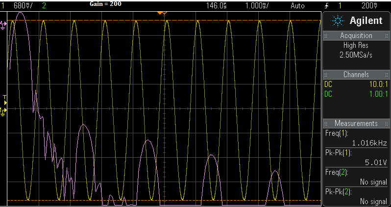
4. Gain = 200 Mode -- plus lifting and AC bypassing Pin 2
Last section. Here's the famous schematic used by millions to make simple DYI audio projects:

Connecting Pins 1 and 8 AC bypass a 1.35K emitter resistor in the input pair -- and unleash the hounds. We get a full menu of gain, noise, and potentially harsh sounding distortion.

Above —In this separate experiment to showcase the worst-case scenario, I've manipulated & then pushed this particular amp into raucous distortion. Note the strong 3rd and 5th harmonics relative to the 2 even harmonics. This is worst case fuzz box stuff. While this might sound bad with your ears, it's great fun to see it on a DSO.
Above — Back to the main experiments using the schematic shown above... The FFT at 5 Vpp or 372 mW output power. The 2nd harmonic lies at -46 dBc.The various tones do not go down much at lower input signal levels.

Above — Increasing the signal generator output to push the amp into clipping. The 3rd harmonic looks ready to break open.
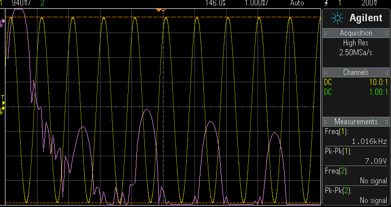
Above — A slight increase from 7.01 to 7.09 Vpp. The 3rd harmonic is about 41 dB down.When in full gain mode, the LM386 tends to offers more odd harmonics

Above — Top and bottom sine wave clipping translates into wretched distortion.
My question -- will feedback similar to what we used in the Bass Boost variants lower the harmonic distortion?

Above — At our standard of 5 Vpp, the affects of feedback leap out at us. [ 10K plus 0.01 µF cap ] Feedback is our friend? However, the gain dropped to around 100 and you will hear lots of high frequency roll off.

Above — Vpp = 5 with a feedback network consisting of a 10K + 0.001 µF cap. The response is lack luster compared to 10K + 0.01 µF capacitor. The drop in voltage gain was only 2%. The 2nd harmonic is maybe 1-2 dB better than without the feedback network?

Above — Vpp = 5 with a feedback network consisting of a 10K + 220 pF capacitor. Interesting FFT ! The 2nd harmonic is now -50 dBc where without the network it measured -46 dBc.. Some of the tones dropped around 4 or 5 dB too. No change in voltage gain by adding this network.

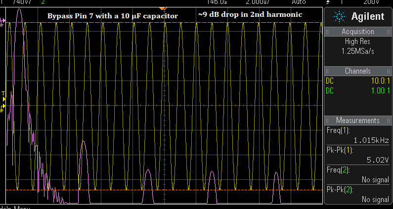
Above — There's an old trick left to try. Normally, most builders will ground Pin 2 like I did throughout this blog post. What if we AC couple Pin 2 to ground through capacitor C2?. This may help to better DC balance the input pair bases ( may reduce DC offset ) and perhaps even bypass some portion of the distortion to ground.
Does this work?

Above — The FFT tracing shown above is with C2 in place showing that C2 does decrease distortion in certain cases. I could not superimpose 2 FFTs, so I made a red line above each of the 4 harmonic tones.
The bottom of the red line is the exact peak of the each tone with Pin 2 shunted to ground. Above the red line is the measured improvement for that particular tone caused by C2. I installed a switch across the C2 capacitor to make comparisons. . C2 = 0.01 µF in this particular experiment.
In my experiments with a gain of >=150 and no feedback network, when the LM386 is pushed into harmonic distortion, C2 lowered the harmonic tones by 4 to 8 dB. I tried C2 values of 0.01 to 0.27 µF
and changing the value of C2 within that range seemed to make no significant difference. Replacing C2 with a resistor of any value did not work to lower distortion.
C2 seemed to have less of an effect when the LM386 gain was lower than 150. At Gain = 20 with no feedback, I observed a maximum 2-3 dB maximal improvement in any 1 tone. With feedback, the effect diminished a little further, however, results were inconsistent. C2 does not appear to lower the harmonic distortion when the audio signal is unclipped -- rather, it seems to reduce distortion due to clipping when it happens.
I performed other experiments such as bringing the feedback to Pin 2 with Pin 2 connected to ground via a resistor or resistor + capacitor (like what you do with an op-amp or discrete AF amplifier). I also tried lowering the feedback 10K resistor value at various gain levels. Often enough, the result was that the LM386 would go into a writhing spasm when pushed into distortion. See below.

Above —Fancy feedback experiments often resulted in the above tracing. It seemed better to explore simpler ways to lower distortion.
Conclusion
Wow, this was a lot of work, but proved fun. I encourage you to perform your own experiments with the LM386. While no panacea, and a little long in the tooth, the LM386 reflects a simpler, mostly analog time for many of us home builders.
I suggest you consider using the LM386 with lower gain and build up your audio signal voltage with a low noise preamp using an op-amp like the NE5532.
Further, consider adding feedback [ 10K plus some value of C1 ] from Pins 5 to 1 and also AC coupling Pin 2 to ground. I did both of these tricks in my 2 photographed bench CD player listening tests shown in Section 2.
とてもいい